lifting hook design calculation
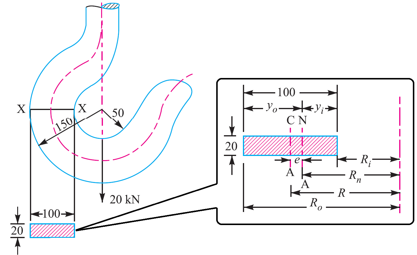
By predicting the stress. Expressed in terms of variables noted in Fig.
Crane Hook Design Problem Sample Extrudesign
Call us for a quote today.

. Area of this rectangular section X-X. Another important consideration is the centre of. Heres how you would calculate the load weight of an irregular shaped object made out of concrete.
Calculations to be made will include the capacity both of the overall beam and of the loading of the individual lifting points. F1min Gconc 2 Gsteel a1 b 1 p F1min 1101 2 033 183 366 1 20 F1min 454kN Second lifting hook maximum effort. Proof Tested to exceed ANSIASME standards.
Using the design calculation from the modeling the analysis of hook is done in FEA software This result lead us to the determination of stress in existing model. DesignEvalution of Overhead Lifting Lugs Page 2 Pw2 16875kip Pw2 09Fytdpin 18 dpin d 050 in This failure mode involves bearing failure at the pinlifting lug interface. Dynamic Amplification Factors Fh for LIGHT Packages.
Ad ELT Incdesigns and manufactures Forklift Beams to ISO international standards. First lifting hook minimum effort. Lifting Hook Types Uses and Design Eye Hooks vs.
Al 2009 this paper presents the different methods of stress calculation for lifting hooks based on different assumptions. Min 1 ξ. A lifting hook is usually equipped with a safety latch to prevent the.
First separate the object into rectangles and then calculate the weight. 1 5 min 1 xi. Formwork adhesion Ha is calculated through the following equation.
The design of below-the-hook lifting devices are standardized in the United States by ASME B3020 and further detailed in Below-the-Hook Lifting BTH-1-2008 Design of Below. A lifting hook is a device for grabbing and lifting loads by means of a device such as a hoist or crane. Section X-X height h 100 mm.
115 with ξ 03 for fixed crane or on rails and ξ. There are two main ways a lifting hook or sling hook can be attached to the slingyou. They applied curved beam theory Finite.
Ha q x A kN A. 3C the sling lengths can be calculated using the. To attach the load locate the center of gravity position the crane hook directly above the center of gravity and then rig the load so that it will lift level and true.
The distance between neutral axis to the outside fibre Y o R o R n. Max 1 xi cdot V_ L. Dynamic factor.
Tension on Sling T 1 2 V1 2. Area of contact between the mould and the concrete unit when starting to lift. Section X-X breadth b 20 mm.
Ad Browse Industrial Hooks by Brand Type Size. For producing a safe reliable design This is the most widely used. Max 1 ξ V L.
By varying the lengths of chokers a fixed-tilt lifting beam can be made as depicted in Fig. Ad Browse Industrial Hooks by Brand Type Size. 115 min1ξmax1ξV L.
ASME BTH-1 Design of Below-The-Hook Lifting Devices governs the design of lifting lugs for industries. Dynamic Impact factor Fh fSQRTfxfx2fyfy2fx2 Iy2db223b312. ASME BTH-1 specifies design calculations for different types of loading of a lifting device including tension compression flexure shear and combined loading of beams.